120 230 Motor Wiring Diagram
Wiring diagram for single phase motor fresh pretty single phase. The advantages of a 240 volt motor.
120 Volt Capacitor Start Motor Wiring
Some motors allow both 120 volt and 240 volt wiring by providing a combination of wires for doing so.
120 230 motor wiring diagram. (remove red wire connecting x2 to l2). Each part should be set and linked to other parts in particular way. A universal electric motor is designed to operate on either alternating current or direct current (ac/dc).
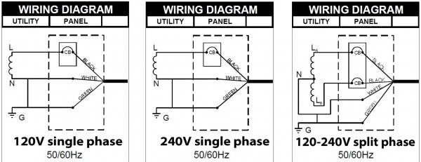
In this video jamie shows you how to read a wiring diagram and the basics of hooking up an electric air compressor motor. The diagram that shows connection for 115 or 230 is missing. Single phase motors are used to power.
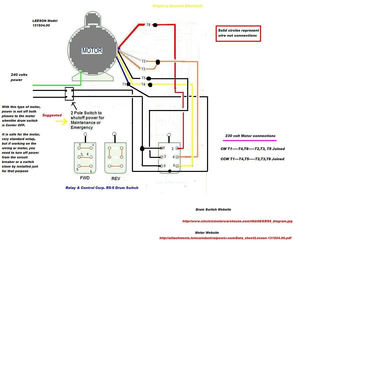
Coil above is wired for 230 v to. For specific leeson motor connections go to their website and input the leeson catalog # in the review box, you will find connection data, dimensions, name plate data, etc. The first step is to figure out the voltage of your phases.
If any of the original wire as supplied with the furnace must be replaced, it must How to wire a three phase motor. These diagrams are current at the time of publication, check the wiring diagram supplied with the motor.
The objective is the exact same. That being said there is a wide range of different motors and what you have on hand. Hi, i am a me with very limited knowledge on electrical side of the world.
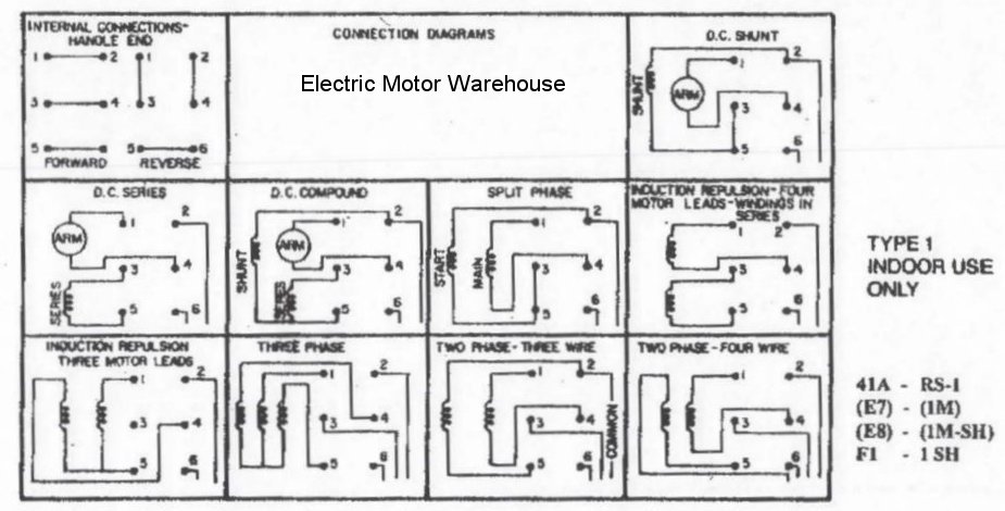
Terminal markings and internal wiring diagrams single phase and polyphase motors meeting nema standards see fig. Refer to the motor manufacturer’s data on the motor for wiring diagrams on standard frame ex e, ex d etc. Rewire red wires at coil.
In the united states, for low voltage motors (below 600v), you can expect either 230v or 460v. 2 pole 3 phase motor wiring diagram fresh wiring diagrams for single. For supply connections use copper conductors only.
With larger motors there may be a larger junction box with lead wires that are identified with numbers or letters which will be identified by the wiring diagram of the specific motor. Wiring a motor for 230 volts is the same as wiring for 220 or 240 volts. It is a series wound motor.
Electric motor wire marking & connections. It reveals the parts of the circuit as streamlined shapes and the power and signal connections in between the gadgets. Residential power is usually in the form of 110 to 120 volts or 220 to 240 volts.
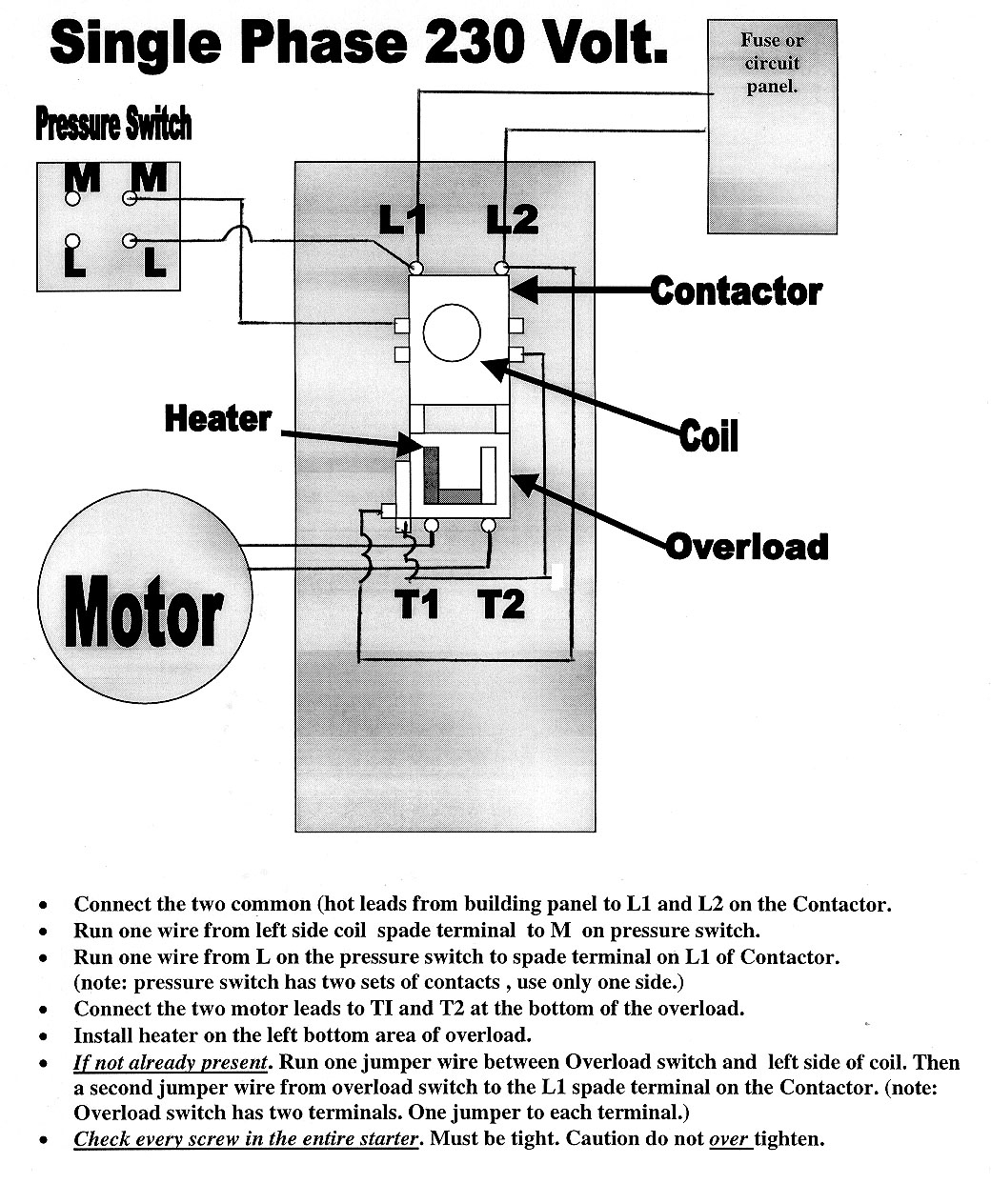
It is provided with a field winding on the stator which is connected in series with a commutating winding on the rotor. Collection of air compressor wiring diagram 230v 1 phase. Look at the wiring diagram for your specific hvac equipment and find the.
This electric motor capacitor article series explains the selection, installation, capacitor to get an air conditioner motor, fan motor, or other electric motor running. 230 volt single phase motor wiring diagram database. A wiring diagram is a streamlined conventional pictorial representation of.
Disconnect all power before servicing. Each component ought to be placed and linked to different parts in. Two speed, one winding, vt or ct m/s, single voltage:
Two speed, one winding, chp m/s, single voltage That being said, there is a wide range of different motors and what you have on hand. Wiring diagram 230v single phase motor.
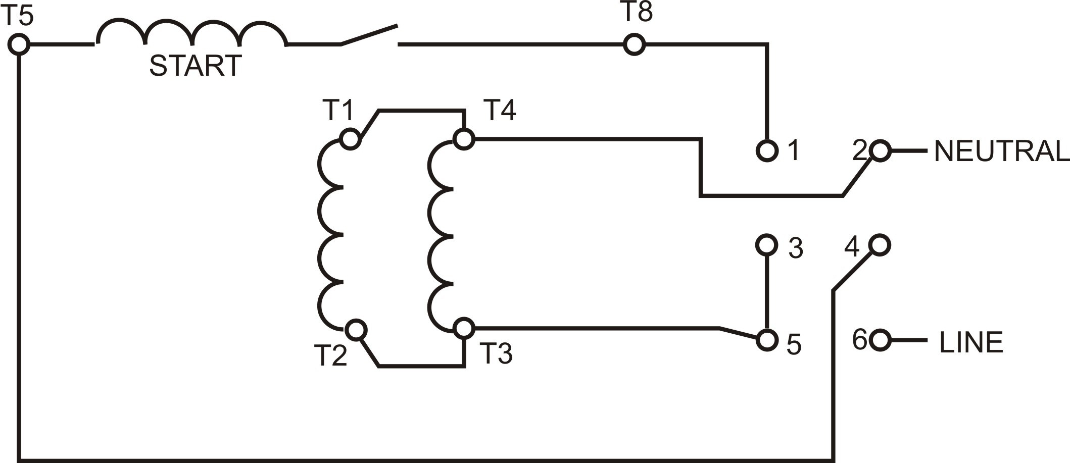
230 volt single phase wiring diagram. How to change rotation on a dayton 120 volt ac motor. Coil above is wired for 230 v to pump motor, 120 v from isotrol or dispenser switch.
Variety of baldor single phase 230v motor wiring diagram. Such motors will typically have six leads coming out of the motor to the wiring box, or some of the connections may be screw terminals. Variety of baldor single phase 230v motor wiring diagram.
Up to 20% cash back i have a ge electric motor that can be used on 115 0r 230 volts. Systems are in the compressors and their relays. Wiring a 120/240 volt motor for 240 volts is as follows:
I want to use it on 230 volts. Inst maint & wiring_5.qxd 20/11/2015 11:37 am page 7 Wiring a 120/240 volt motor for 240 volts is as follows:
Inst maint & wiring.qxd 5/03/2008 10:02 am page 6 220v single phase motor wiring diagram wiring diagram is a simplified good enough pictorial representation of an electrical circuitit shows the components of the circuit as simplified shapes and the capability. In north america, many single phase motors motors in the range of 1 hp to 2 hp can be rewired to run at either 120 volts or 240 volts (or 115 vs 230 volts, it depends on what voltage is assumed nominal).
Airflow airflow airflow airflow * * these diagrams are current at the time of publication, check the wiring diagram supplied with the motor. Orange red blue blue black t1 l1 l1 l2 l3 l2 l3 x2 t2 t3 to 208/230v supply coil 3421 3 to stp (see diagram g) note:
120 208v Single Phase
120 240 Volt Motor Wiring Diagram easywiring

Electric Motor Wiring Diagram 110 To 220 Cadician's Blog
Yet another drum switch novice

Deep Red A selfbuild motorhome Mains 230v

480 Volt 3 Phase Motor Wiring Diagram 120 240 Volt Motor Wiring Diagram schematic and wiring
Wiring Diagram for Air Compressor Motor Collection

Electric Work Wiring Diagram 230 Volt

Wiring Diagram For 120 Volt Light Switch 25
Bought used bridge port need help to plug it in!

4 Wire 50 Amp Wiring Diagram Manual EBooks 240 Volt Wiring Diagram Cadician's Blog
208 Volt 3 Phase Wiring Diagram THEINSTRUMENT

230 Volt Single Phase Motor Wiring Diagram Database Wiring Collection
Doerr Electric Motor Lr22132 Wiring Diagram Cadician's Blog
Solarex 120 Watt Wiring Diagram 12/24 Volt 3 Century ac motor wiring diagram 115 230 volts.
230 Volt Motor Wiring Diagram
115 230 Volt Century Electric Motor Wiring Diagram Wiring View and Schematics Diagram
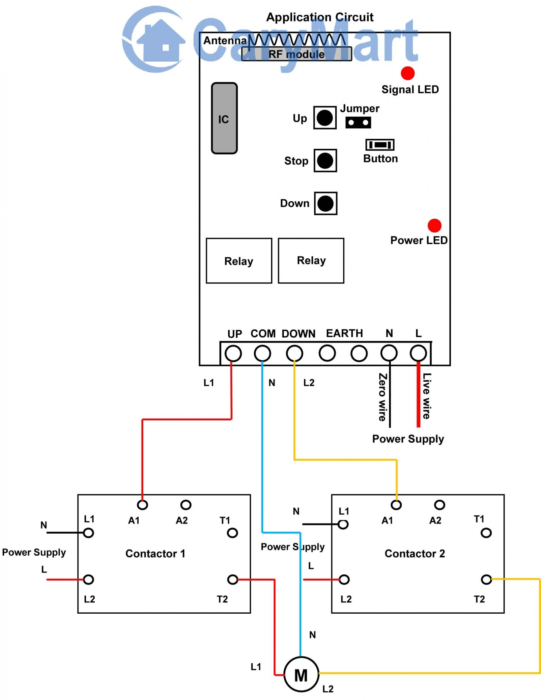
Hunter Pump Start Relay Wiring Diagram Sample

230 Volt Single Phase Motor Forward Reverse Wiring Diagram
