9 Lead Dual Voltage Motor Wiring
For most connections, the only. Electric motor wire marking & connections.
12 Lead Motor Wiring Diagram Discover The World Of
12 lead motors are not common but may be connected in series parallel, or star delta for 4 voltages.
9 lead dual voltage motor wiring. This video will walk you through the standard winding terminal designations, proper wiring connections, and expected winding voltages for a dual voltage, 3 p. Each lead may have one or more cables comprising that lead. High voltage connection for wye or y.
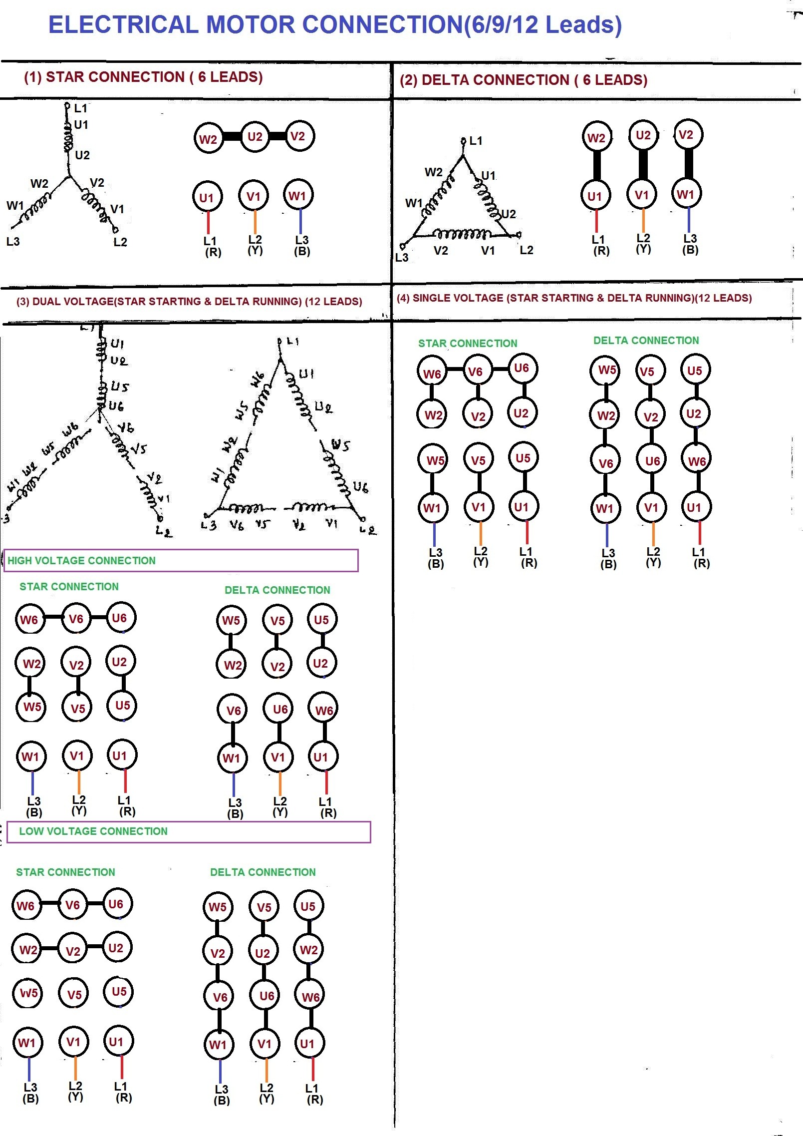
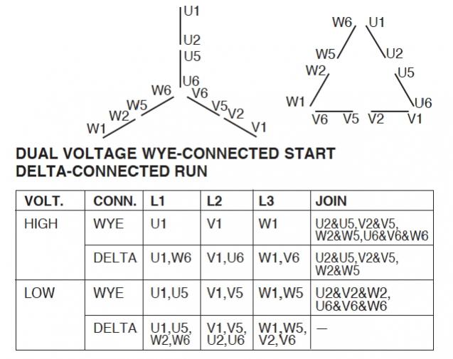
Motor wiring diagram 12 lead, dual voltage, wte start / delta run, both voltages € € € € € € us electrical motors per nema mg1 , a wye start, delta run motor is one arranged for starting by connecting to the supply with the primary winding initially connected in wye, then reconnected in delta for running condition.12 lead motor. 9 lead motors can be either dual voltage wye or dual voltage delta (again, you won't know the difference), typically 230/460v. When you make use of your finger or perhaps the actual circuit with your eyes, it is easy to mistrace the circuit.
Low voltage connection for wye or y connected, aka wye wound, 9 lead, 3 phase, dual voltage motor. Connected, aka wye wound, 9 lead, 3 phase, dual voltage motor. Dual voltage single phase motor wiring diagram from media.cheggcdn.com.
The nema 9 lead configuration can be either star or delta, but cannot be changed with the external leads. On delta connected motor lead #s (7,8, & 9), (1& 4), (5& 2), (3& 6) have continuity with each other on wye connected motors (1,4& 9), (3,6 & 8), (7,2 & 5) have continuity with each other. For the wye start, dual voltage nine lead motor.
Each motor will have 9 numbered leads coming out of the motor. Connecting these is a bit more complicated, and mistakes are actually common. Those nine leads provide an option for supplying power from either high or low voltage sources.
1 trick that we 2 to printing a similar wiring plan off twice. Three phase slip ring rotor starter control power power electric circuit electricity magnetism. You can usually wire them only for a delta start.
3 phase 6 lead motor wiring diagram welcome to our site this is images about 3 phase 6 lead. High voltage 1 wye jumper bars u2 v2 w2 l1 l2 l3 u1 v1 w1 u5 v5 w5 u5 u2 v2 w2 l1 u1 l2 v1 l3 w1 v5 w5 bronze screws a. Low voltage 2 wye b.
Each lead may have one or more cables comprising that lead. In such case, each cable will. Electrical motors 12 lead dual voltage wye start delta run both voltages or 6 lead single voltage wye start delta run motors designed by us motors for wye start delta run may also be used for across the line starting using only the delta connection.
Print the wiring diagram off plus use highlighters to trace the signal. The term refers to the. The leads are numbered to aid the electrician when connecting the motor.
480v 3 phase motor wiring diagram. In some rare cases you will see iec motors sold in n. Typically, these motors don’t permit a wye start with delta run;
Ratios of 1/1.73/2/3.46 or 220 volts, 380 volts, 440 volts, 760 volts. For specific leeson motor connections go to their website and input the leeson catalog # in the review box, you will find connection data, dimensions, name plate data, etc. Wye motor high voltage connection 9 lead wiring diagram.
3 lead, single voltage b. Normal iec motors are 6 lead, star delta, for two voltages in the ratio of 1.73/1. For high voltage, the wiring changes:
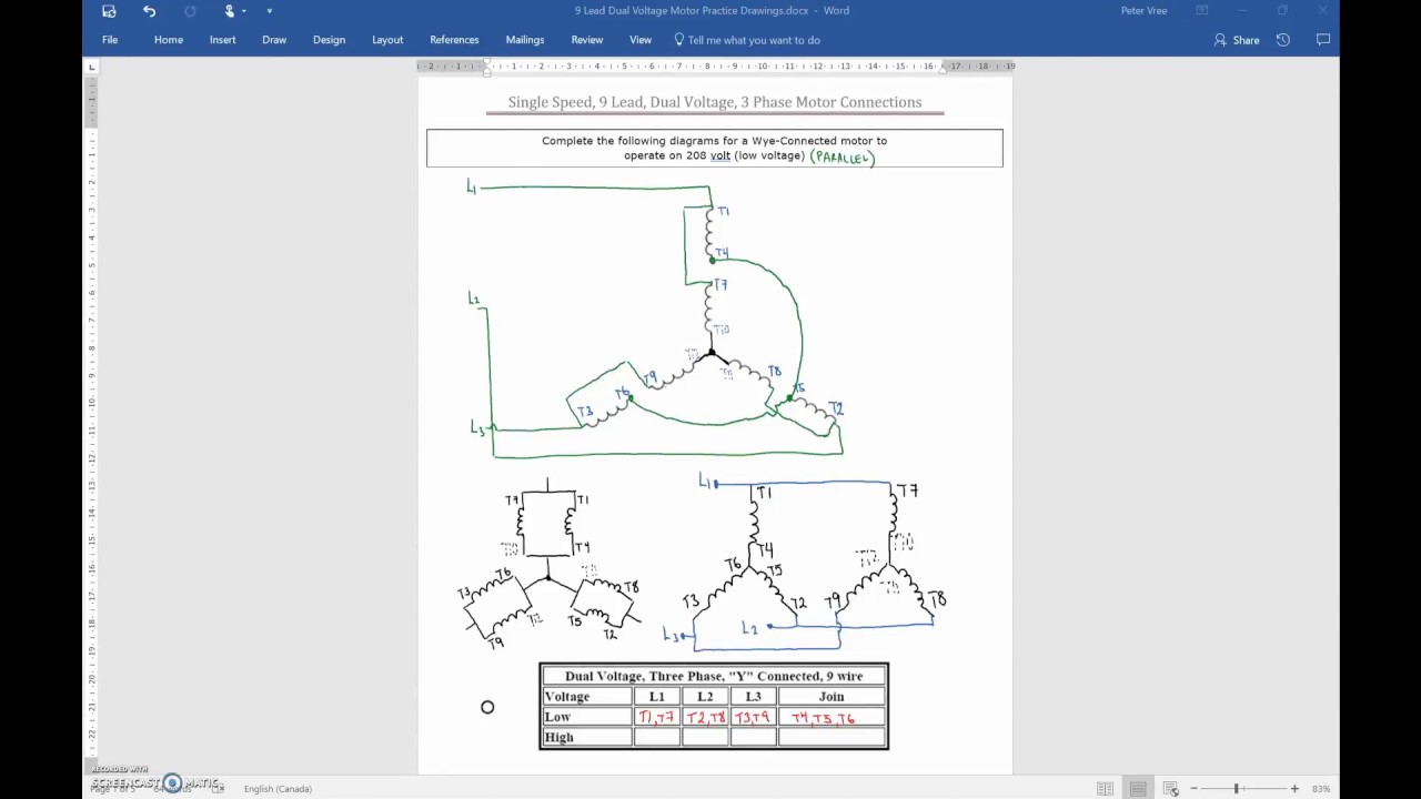
America as single voltage 9 lead motors, because they base it only on the high voltage connection (wye only). Normal nema motors are 9 lead series parallel, for two voltages in the ratio of 2/1. Wiring dual voltage wye connected motors low voltage l1=1&7, l2=2&8, l3=3&9, join 4,5&6 high voltagel1=1, l2=2, l3=3 join 4&7, 5&8, 6&9
The term refers to the configuration of the connections between the coils of the Motor wiring diagram 9 lead, dual voltage, wye connection part winding start (pws) on low voltage to reverse direction of rotation, interchange leads l1 & l2. The higher voltage connections are the same but the lower voltage connections are different.
High voltage 1 wye a. The wiring diagram for a wye connected 9 lead motor is as follows:. But there are exceptions (iec motors, for example).
In addition, all three have six internal coils, although their internal connections differ widely. In such case each cable will be marked with the appropriate lead number. For the low voltage option, the instructions show to connect the following:
Shown below are representations of the wiring connections made to european motor terminal blocks. Configuration of the connections between the. The 3 phase dual voltage motors i have seen have 9 leads.
Low voltage 1,7 2,8 3,9 4&5&6 high voltage 1 2 3 4&7, 5&8, 6&9 in this case, high voltage connections are the same as for delta motors. Low voltage 1 delta a.
Weg 12 Lead Motor Wiring Diagram
3 Phase Motor Wiring Diagram 9 Leads Wiring Diagram Schemas
9 Lead Motor Wiring Diagram For Your Needs

480 Volt 12 Lead Motor Wiring Diagram Https Www

3 Phase Wire Diagram — UNTPIKAPPS

3 Phase Low Voltage Motor Wiring Wiring Diagram

[EO_1610] Phase Motor Wiring Diagrams Likewise 3 Phase 6

[DIAGRAM] Three Phase Drum Switch Wiring Diagrams FULL

3 Phase Motor Wiring Diagram 9 Leads Wiring Diagram Schemas

Motor Wiring Diagram 9 Lead, Dual Voltage, Delta

Motor Wiring Diagram 9 Leads Dual Voltage Single Phase

Polyphase Induction Motors Technovationtechnological

Motor Wiring Diagram 9 Leads Dual Voltage Single Phase

480 Volt 3 Phase Motor Wiring Diagram Dual Voltage
IEC labeling of dual voltage motors with 9 and 12 leads
Wye / Delta Connection Detail Schematics Technical

9 Wire Motor Diagram 3 Phase Motor Wiring Diagram 9

Wiring a 9 lead motor to Drum Switch

Weg 12 Lead Motor Wiring Diagram Collection
